The etiology of pediatric idiopathic scoliosis remains poorly understood and it is likely that there is a combination of different factors responsible for its initiation and development. Although the literature highlights the importance of mechanical factors on spinal deformations, the concepts did not receive the attention and consideration they deserve. The Cobb angle is the gold standard value to assess the extent of spinal deformations and risk of progression. However from a biomechanical perspective, it is not the Cobb angle that prevails but rather the distance from the vertebrae to the axis of an ideal straight vertical spine that is well seated and centered on the sacrum. These vertebral offsets along with asymmetrical loads are responsible for additional bending forces that may reach much higher values than the compression forces of a symmetric same load on a straight spine. Forces can be modified, amplified and redistributed by the shape of the spine alone. This article is a review of biomechanics concepts that are applied to the spine with simple concrete examples, and is addressed to clinicians and practitioners in orthopaedics, physical therapy, and sport and exercise science.
Spine, Biomechanics, Scoliosis, Trunk shift, Musculoskeletal, Posture, Sport
Juvenile and adolescent idiopathic scoliosis (JAIS) is a deviation of the spine that develops during childhood and from which 2% to 3% of the population is afflicted. It is characterized by a principal deformation in the coronal plane that is measured in Cobb angle. Scoliosis typically also involves a rotation of the spine (rotoscoliosis), and spinal deviations in the sagittal plane that may involve the alteration of the normal lumbar lordosis, thoracic khyphosis and cervical lordosis. Scoliosis is usually accompanied by a combination of signs and symptoms, namely a functional (neuromuscular, postural) and/or structural (anatomic, osseous) leg length discrepancy (LLD), pelvic tilt, trunk shift, shoulders obliquity, gibbosity (back hump from the rotation of the rib cage), asymmetry of the posture, obliquity and rotation of the head and neck, back pain, headache and differences of bilateral weight on force platforms.
Determining the risk factors for clinically significant curve progression would allow identifying patients that are more likely to benefit from bracing [1]. The risk factors include namely the pattern and magnitude of the curve, the patient's age at presentation, the Risser sign, and the patient's menarchal status [2]. The aim of this article is to provide a revisited perspective of the overall spinal biomechanics, the sources of forces and stresses, and how they can be modified, amplified and redistributed by the shape of the spine alone.
Although some analytical material is presented to support the biomechanics principles here raised, its comprehension is not necessary to understand the concepts and examples described that are aimed for a variety of readers' health and sport disciplines and background.
Starting from the occipital foramen (C0, i.e. base of the head), the spine is composed of 7 cervical vertebrae (C1-C7), 12 thoracic vertebrae (T1-T12) and 5 lumbar vertebrae (L1-L5), for a total of 24 vertebrae, and sits on the rigid structure of the sacrum composed of 5 fused vertebrae (S1-S5), and finally the coccyx composed of 4 fused primitive vertebrae.
Each of the 24 mobile vertebrae consists of a rigid bone structure able to rotate, some more than others. Vertebrae are composed of an anterior structural part called vertebral body that supports the load, a posterior canal that insures the protection of the spinal cord from the brain down to the last lumbar vertebra, and some processes (Figure 1). The vertebrae (except at the C0-C1 and C1-C2 junctions) are separated by discs that allow for smooth movements and are held together by ligaments and muscles.
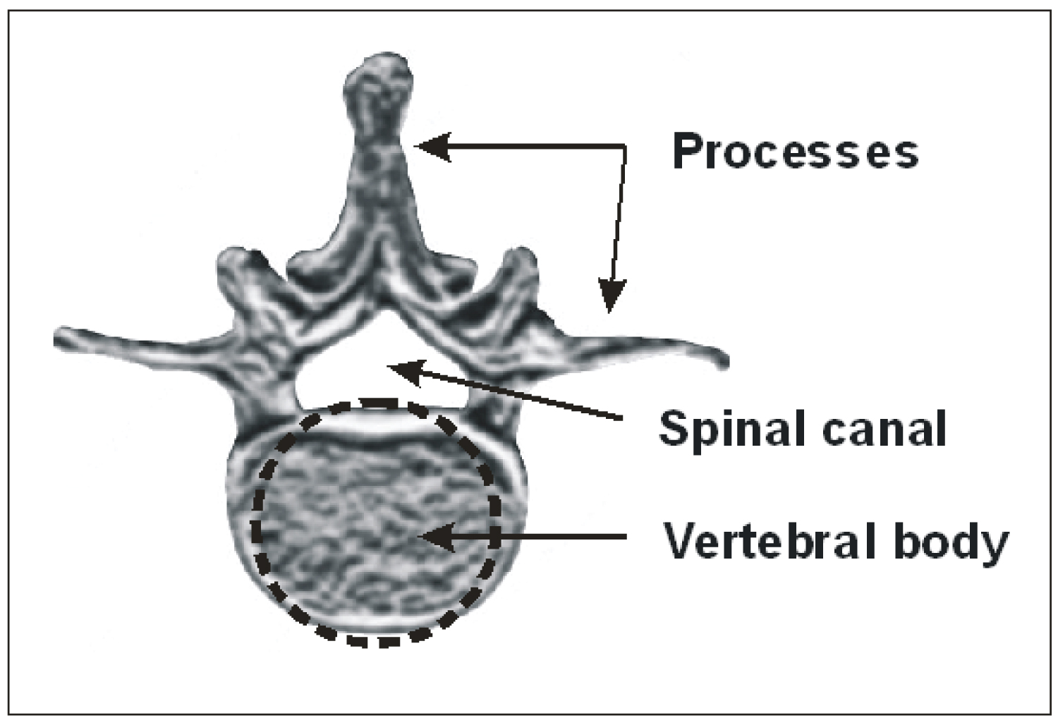 Figure 1: Illustration of a lumbar vertebra.
View Figure 1
Figure 1: Illustration of a lumbar vertebra.
View Figure 1
Forces applied on the trunk and spine may arise from different sources, namely 1: The load of the upper body weight (BW). 2: The weight from carrying a load. 3: The dynamic forces from a muscular effort to accomplish a task such as lifting, pushing or pulling. 4: The dynamic forces from cceleration/deceleration from a jump, a fall or a sport. All these forces on the trunk are redirected, modified and redistributed by the bones, muscles and ligaments to the structural part of the trunk that is the spine. These forces and stresses may also be modified in amplitude and distribution as a function of the spine geometry and trajectory.
The most basic but important law about forces has been stated by Isaac Newton (1643-1737) as below:
F = m.a (1)
Any mass (kg) in a gravitational field is submitted to gravitational forces (N) resulting from the earth attraction. From Eq.1, the gravitational forces (Fg) are equal to the product of the mass by the gravitational acceleration (g = 9,8 m/s2). In this article, we will take the example of a 70 kg (154 lbs) youth for the calculations of forces and stresses. Shields [3] reported that the average weight for Canadian boys aged 12 to 17 was 64 kg (140 lbs). The difficult choice of this arbitrary value was favored because it represents the weight of some North American high school teenagers and because anatomical dimensions of vertebrae are scarce, particularly for children. The values of forces and stresses herein calculated can be adapted proportionally to any child's weight, provided that the child's vertebrae areas are also considered. Nevertheless, for any weight and age the principles here raised remain the same. For example, the gravitational forces exerted on a 70 kg youth standing on the ground can be calculated as below:
Fg = m.g (2)
Fg = 70 (kg). 9,8 (m/s ) = 686 N
Ex.1: Gravitational force of a standing 70 kg youth.
Forces applied on the body can be divided in two categories: The static forces and the dynamic forces. Static forces involve no movement and being in a state of equilibrium, like an individual standing still. Any static system must comply with the following equation where the sum (∑) of all the forces in any direction must equal zero.
∑F = 0 (3)
Dynamic forces involve a mass in movement that may include acceleration (or deceleration), such as jumping, lifting or throwing a weight. A resultant force that does not equal zero (not static i.e. ∑F ≠ 0) will involve acceleration of the mass.
The global structural behavior of the spine can be represented by a simplified model that is a solid bar of length "ℓ" with different sections representing the different vertebrae with their respective radius "r" and area "A". Although this model is simple, it is sufficient to understand the basic overall spinal mechanics involved in the support of the different forces and stresses, along with different spinal shapes and trajectories.
In this article, the model used does consider the spine only. Although the muscles and ligaments do play an important role to maintain the spinal integrity, redistribute the forces exerted on the trunk and transfer them to the spine, overall, the spine remains the structural part of the trunk that supports the most of the forces. Muscles and ligaments, as opposed to bones, are soft biological tissues that work mostly in traction, and therefore their overall contribution to reduce the load exerted on trunk and transmitted to the pelvis is limited.
The complex consideration of redundant number of muscles and ligaments by means namely of analytical and numerical finite elements analysis is beyond the scope of this article which aims to raise the principles that overall dictate the essentials of spinal biomechanics. Nevertheless, despite this limitation, the principles and examples herein presented should be seen as an approximate comparative qualitative static analysis of different loads, asymmetries and spinal deviations/deformations configurations for a given musculature and ligaments contribution of one individual.
The spinal structure, forces and stresses may be described in a three dimensional orthogonal coordinate system with the x, y, z axes crossing each others at a center point of origin (0,0,0) located at the base of the spine, at the centroid of the L5 and S1 lumbosacral junction (L5S1), hereafter called CL5S1 (Figure 2A). From that CL5S1 is drawn a vertical line (VL) of reference thereafter called CL5S1VL that corresponds to the z axis. A normal spine should therefore be aligned with the CL5S1VL in the coronal plane. In this figure, a force "F" is applied at the base of the spine. To comply with Eq.3, this force F will generate an equal reacting force in an opposite direction "-F" at the L5S1 junction (from the sacrum) for reaching a static equilibrium (i.e. ∑F = 0).
 Figure 2: (A) Schematic of the spine from head to sacrum, and the coordinate system. The spine is loaded with a force "F" at the T1 level and aligned with the sacrum CL5S1VL, resulting in a "-F" reacting force from the sacrum; (B) Representation of a deviated spine loaded with a force "F" at the T1 level at a distance "d" from the CL5S1VL, resulting in a "-F" reacting force and a bending moment "M" (because of the offset "d") at the L5S1 junction.
View Figure 2
Figure 2: (A) Schematic of the spine from head to sacrum, and the coordinate system. The spine is loaded with a force "F" at the T1 level and aligned with the sacrum CL5S1VL, resulting in a "-F" reacting force from the sacrum; (B) Representation of a deviated spine loaded with a force "F" at the T1 level at a distance "d" from the CL5S1VL, resulting in a "-F" reacting force and a bending moment "M" (because of the offset "d") at the L5S1 junction.
View Figure 2
In the context of this article, we will emphasize the stresses applied on the spine in the vertical gravitational axis (z) and subdivide them into two main types: The compression stress and the bending stress. The mechanics and examples are herein presented in the coronal (frontal) plane, but they can also be applied in the sagittal plane. The compression forces and stresses are uniaxial (compression or tension). A stress "σ" (N/m2 = Pa) is defined in Eq.4 as a force divided by the perpendicular area to which the force is applied.
If we consider the area to be circular (as a solid bar), or if we want to approximate a more complex area (as a vertebral body) by its equivalent circular area, we then obtain from Eq.4 the following compression stress:
We could estimate an approximate stress value at the lower end of the spine (L5S1) resulting from the weight of the trunk for our 70 kg youth. We will herein consider that the trunk, arms and head weight (TAHW) represents approximately 2/3 of the whole BW to be supported at the L5S1 level [4-7]. The vertebral body is roughly circular and we will approximate its area to that of a circle. Busscher [8] reported standard L5S1 vertebral body junction width and depth values of about 55 mm and 40 mm respectively. We can therefore approximate the L5 vertebral area (πr2) of A L5S1 = 2 × 10⁻³ m2 at the L5S1 junction. According to Eq.5 we would then obtain a compression stress of 230 kN/m2 arising from the TAH weight.
σL5S1 = F. (2/3)/AL5S1 = 686 N × (2/3)/(2 × 10-3 m2) = 230 kPa
Ex.2: TAH gravitational compression stress at the L5S1 level of a 70 kg youth.
Another mechanical concept of importance is the bending moment "M". Figure 2B illustrates a deviated spine on which a force F is applied at the T1 level at a distance "d" from the CL5S1VL. The force "F" and its equal and opposite reactive force "-F" generated at the sacrum will create a tendency for the spine to pivot counterclockwise because they are separated by a distance "d".
M = F.d (6)
In order to reach the static equilibrium, the sacrum will not only have to comply with a null resultant force -F (Eq.3), but also with a null resultant bending moment "M":
∑ M = 0 (7)
The spine is anchored at its base to the pelvis (i.e. sacrum and iliac structures) which transfers the load to the legs and then down to the feet. From Eq.3, any vertical force applied on the TAH will have to be supported by an equal force in the opposite direction from the sacrum to reach a state of equilibrium. If the forces applied on the spine are not on the same vertical axis than that of the opposite reactive force from the sacrum (CL5S1VL), then a bending moment will be generated (Figure 2B). The bending moment will result in some bending stresses that can be defined by Eq.8, where "σB" is the bending stress, "r" is the radius of the solid bar segment (or vertebral body), "I" is the second area moment (πr4/4), and "d" is the distance between the vertical axis where the force is applied to the vertical axis of the reacting force at the center of the vertebra of interest (at the L5S1 junction for instance). The bending stresses calculated are the maximum and the minimum values located at the perimeter of the vertebra on the x-axis. The bending stress decreases linearly from the maximum value (one side of the vertebra) to the minimum value (negative at the other side of the vertebra), and equals zero at the vertebral body centroid.
We can give the example of a 70 kg youth holding a 5 kg school bag (i.e. 7% of a 70 kg BW) and consider the gravitational compression force from the school bag on the body, regardless of its distance from the spine. According to Eq.5, the gravitational force generated by the school bag alone will cause a uniform compression stress of 25 kPa exerted on the lumbosacral junction L5S1.
σ = F/AL5S1 = 5 × 9,8/2 × 10-3 m2 = 25 kPa
Ex.3: Gravitational compression stress at the L5S1 arising from a 5 kg school bag centered (no bending).
To demonstrate the effect of the bending stress we can keep our example of a 70 kg youth holding a 5 kg school bag along the body and with a distance d = 0.25 m between the center of the school bag and the CL5S1VL. The bending stress at the L5S1 junction would then be of σB = 1000 kPa:
Ex.4: Bending stress at the L5S1 level arising from a 5 kg school bag held along the body at d = 0,25 m from a straight centered spine.
We can also consider the same school bag example but with an overreach value of d = 0,5 m from the CL5S1VL, equivalent to nearly one half of fully deployed arms (as in the case of placing the school bag upon a shelf or table). Since the bending stress is proportional to the distance "d", twice the distance would result in twice the bending stress and therefore σB = 2000 kPa. It is interesting to note that a 5 kg school bag carried along the body will generate 40 times more stress from the bending than that of the school bag weight alone (gravitational compression) well centered on the CL5S1VL (1000 kPa vs. 25 kPa). The same school bag held at d = 0,5 m from the CL5S1VL leads to an additional bending stress 80 times larger than that of the school bag's weight centered. Bending stresses may reach much higher levels than those of their corresponding compression stress well centered. This example illustrates the importance of the bending stress in spinal biomechanics and how heavily it depends on the horizontal distance "d" of the force from the spine.
There are also some 3D shear (transverse) stress considerations but their contributions to the overall level of stress exerted on the spine are usually of a lesser amplitude than those involved along the gravitational axis (z). On the other hand the spinal structures loaded in shear are weaker [9].
Each force applied on a mass results in a stress. When there are different forces applied on the same mass, all of the different stresses that arise from their respective forces have to be added together to obtain a total resulting stress (σT).
σT = ∑ σ (9)
If we analyse the forces and stresses applied at the base of the spine (L5S1) of our 70 kg youth holding a 5 kg school bag held out at 0,5 m, the overall compression stress will be equal to the gravitational effect of the TAH weight and that of the school bag weight. To this total compression stress must be added the effect of the bending stress. The resulting total stress (σT) at the L5S1 vertebral body perimeter crossing the x axis will be equal to the total compression stress plus or minus that of the bending stress (depending on the side of the vertebra) as follows:
σT = ∑ σ = σC-trunk + σC-school bag ± σB-school bag
σT = 230 kPa + 25 kPa ± 2,000 kPa
= -1,745 kPa or 2,255 kPa
Ex.5: Total stress at the L5S1 level (depending on the side of the vertebra) arising from trunk weight and a 5 kg school bag held at 0,5 m from the spine.
Therefore the total stress applied on the L5S1 junction of a 70 kg youth holding a school bag at 0,5 m from the spine axis equals to a σT = 2 255 kPa on the side of the vertebra (closer to the school bag), and a tension stress of σT = -1,745 kPa on the other side.
The following illustrations (Figure 3) aim to summarize the different impacts on the stress level for different situations of scoliosis, trunk shift and weights carrying depending on their position with respect to the CL5S1VL. These examples illustrate that for a same Cobb angle, other spinal deviations may add or subtract "d" values having more influence than the effect of the Cobb angle. Also worthy to mention another limitation of the Cobb angle is that it does not consider that for a given Cobb angle, a segment that includes a larger number of vertebrae will involve more distancing of the segment from the CL5S1VL (i.e. more vertebrae involving "d "values, and higher "d" values for each vertebra of the segment) resulting in an increase of the cumulative vertebral contribution to the stress at the L5S1. In these examples, the bending stress, and therefore "d", was analysed at the L5S1 junction, however any other vertebra can be analysed with the same concepts along with a "d" value assessed consequently.
 Figure 3: Different examples of spinal trajectories and loads. (A) Scoliotic spine; (B) Counter clockwise trunk shift and pelvic tilt; (C) Scoliotic spine with additive counter clockwise trunk shift and pelvic tilt (A + B); (D) Scoliotic spine with some subtractive clockwise trunk shift and pelvic tilt (A - ½B); (E) Opposite effect of symmetrically loaded spine from school bags along the body (no resultant bending stress); (F) Asymmetrically loaded spine from a school bag held at one half of a fully deployed arm. All Cobb angles in the figure are the same. The light cervical vertebrae and head behind the dark gray spines in Figure B, C and D represent an optional presence of some head recentering that may affect some "d" values for a same given Cobb angle. As opposed to the Cobb angle, the "d" value is proportional to the bending stress.
View Figure 3
Figure 3: Different examples of spinal trajectories and loads. (A) Scoliotic spine; (B) Counter clockwise trunk shift and pelvic tilt; (C) Scoliotic spine with additive counter clockwise trunk shift and pelvic tilt (A + B); (D) Scoliotic spine with some subtractive clockwise trunk shift and pelvic tilt (A - ½B); (E) Opposite effect of symmetrically loaded spine from school bags along the body (no resultant bending stress); (F) Asymmetrically loaded spine from a school bag held at one half of a fully deployed arm. All Cobb angles in the figure are the same. The light cervical vertebrae and head behind the dark gray spines in Figure B, C and D represent an optional presence of some head recentering that may affect some "d" values for a same given Cobb angle. As opposed to the Cobb angle, the "d" value is proportional to the bending stress.
View Figure 3
Scoliosis is quantified in Cobb angle which represents the angle between the upper end surface of the upper end vertebra to the lower end surface of the lower end vertebra of a deviated segment, where a segment is delimited by its inflexion points (i.e. points of zero curvature = null second derivative) as illustrated in Figure 3.
We would like to discuss three types of spinal deformations/deviations: Scoliosis, trunk shift and osseous deformations/remodeling that contribute to the overall spinal deformity and consequent increase and asymmetry of the stress.
Despite all the efforts done so far to understand the factors responsible for the initiation and progression of JAIS, the etiology still remains poorly understood. Although different pathologies are associated with scoliosis, the vast majority of scoliosis remains idiopathic and its diagnosis is one of exclusion. The more a spine is deformed, the more bending stress will be generated, which then will deform the spine even more, resulting in a vicious cycle where more advanced deformations are more likely to develop, in accordance with this concept previously described [10]. A pre-existing scoliosis curve initiates the mechanically-modulated alteration of the vertebral body growth that in turn causes worsening of the scoliosis [11].
Subtle neurological imbalance of the bilateral paravertebral muscles tone could be a plausible causative factor for scoliotic deformation initiation. Spinal growth and imbalance of the paraspinal muscles both result in biomechanical instability leading to progression of the scoliotic curve [12]. The most favored explanation for the pathogenesis of idiopathic scoliosis is neurological [13]. Paravertebral muscles are responsible for stability and correct neuromuscular recruitment patterns between muscles, and they are modulated by the central nervous system [14]. Upper cervical craniocervical junction misalignment may induce a neuromuscular imbalance leading to functional leg length discrepancy and is associated with scoliosis [15]. Among the different pathologies associated to scoliosis we can mention the following: tethered cord, cervicothoracic syrinx, cervical cord tumors, spinal cord injury or craniocervical junction abnormalities [13,16], syringomyelia, low lying cerebellar tonsils, and Chiari malformation [17]. They may interfere mechanically on the spinal cord either directly by impinging on the spinal cord and exerting compression forces and stresses. They may also interfere indirectly by changing the geometry of the spinal canal and therefore disturbing the normal fluid dynamics of the cerebrospinal fluid surrounding the spinal cord, therefore modifying the shear stress distribution on the spinal cord, according to the same biomechanical principles as those involved in vascular fluid dynamics [18,19].
The second type of spinal deviation/deformation arises from trunk shift (lateral shift, side glide) that can be defined as a lateral deviation of the trunk. Scoliosis is not necessarily concomitant with trunk shift and vice versa, however they are often combined. Fortin [20] reported an 85% prevalence of trunk imbalance in their 55 scoliotic patients cohort of 10°-60° Cobb angle and 10-19 years of age.
For a given angle, a deviation that starts at a lower level of the spine may deviate a larger number of vertebrae above than a deviation that starts at a higher level of the spine. Therefore a deviation starting in the lumbar area may be more likely to favor trunk shift than a deviation that starts in the thoracic area. The global trunk shift is the addition of the respective contributions of all deviated vertebrae, and more deviated vertebrae may involve more trunk shift (Figure 3C). This concept may contribute to explain the findings of Fortin et al. [20] who observed a positive correlation of trunk shift among lumbar and thoracolumbar curves.
There has been a growing interest in the literature about trunk shift and different ways to measure trunk shift have been proposed. The C7S1 method is the prevailing method to quantify trunk shift. This method consists in measuring the distance between the CL5S1VL to the vertical line passing through the centroid of the lowest cervical vertebra (C7VL). The horizontal distance between these two vertical lines may define the trunk shift in millimeters, also called coronal balance. There is no consensus on the cut-off value for a diagnosis of trunk shift [21,22], but 20 mm is the most prevalent value, although others have used values ranging between 10 mm and 40 mm [23]. Another method suggested by Zhang [24] to quantify trunk shift is to measure the angle between the C7VL and an oblique line passing through the vertebral centroid of C7 and through the middle of the superior border of the symphysis pubis. The angle between the two lines is an angular description of the trunk shift, with a cut-off value of 2,9 degrees.
However, a patient may be balanced in the coronal plane with the head centered over the pelvis, but still manifest a significant trunk imbalance. Hernandez [21] mentioned that 90% of patients with imbalance were able to keep their head above the pelvis. In their article they used the concept of body contour, and gravity line with force platforms for trunk imbalance assessment. Trobisch [25] therefore suggested assessing the trunk shift by using a horizontal line drawn through the apical vertebra, on which two subsequent marks were drawn on that line at their respective left and right intersections with the thoracic cage. Then a vertical line was drawn at the center (bisectrix) of that segment. The distance from this thoracic center to the CL5S1VL defined the trunk shift, with a 20 mm cut-off value. To avoid the disadvantage associated with the choice of a specific and arbitrary location of the vertebral level at which a trunk shift is measured (namely C7, or apex), and therefore not adapting to the specificity of each patient's deformity and level of head recentering, it might be more reliable and representative of the concept behind trunk shift, to define the trunk shift as the distance of the trunk-arms-head center of mass (TAHCM) from the sacrum vertical line (CL5S1VL), regardless of the spinal trajectory. However, as mentioned Hernandez [21], although the objective localisation of gravity line center of mass using a force platform is more accurate (and representative), it still remains more ill-suited to everyday clinical practice.
Ex.6: Effect of a 40 mm TAHCM deviation on the gravitational bending stress at the L5S1 level for a 70 kg youth.
Therefore, from an original 230 kPa from the TAH gravitational compression stress, a 40 mm trunk shift will cause six times more stress to be added at the L5S1 junction due to the bending effect alone. The bending stress from trunk shift may reach many times the value of the original compression stress and is exerted on the trunk about 16 hours per day.
Scoliosis development and bone deformation, remodelling and wedging are associated with bone growth, and develop especially during the adolescence growth spurt after which they may stabilize. Spinal deviations result in some increased and asymmetrical load on the spine and affect the stress distribution on the vertebral body and on the growth plates, where one side of the vertebrae (on the x-axis) is submitted to higher levels of stress than the other side. It is likely that this uneven stress may affect the vertebra in different ways. With time this increase of stress may cause excessive compression leading to forced mechanical plastic (non recoverable) deformations of the osseous tissue on the concave side, therefore contributing to vertebral wedging. Spinal deformations can result from osseous and cartilaginous deformations but also from discs wedging that may be present even in small scoliotic deformities [26]. It may also affect the trajectory and orientation of the chondrons that are responsible for bone growth. Vertebral longitudinal growth is ensured by the cartilaginous tissue of the physeal plate (growth plate) at the surface of the vertebral body. Located in this area, the chondrons are tubular structures longitudinally arranged and are composed of three different sections. The reserve, the proliferative and the hypertrophic zones. The reserve zone contains the stem cells from which arise the chondrocytes cells that will further divide in the proliferative zone. Thereafter the chondrocytes will increase by several fold their volume in the hypertrophic zone after which they will go through apoptosis and calcify, therefore contributing to the longitudinal bone growth.
Vendra [27] described the behavior of chondrons deformations (strains) under forced compression. Their deformations were observed by confocal microscopy and described by means of their radius of curvature under stress. They observed that the chondrons deformations were focused at certain locations with sharp radius of curvature therefore resulting in some stress concentrations, and possible kinking and buckling. Interestingly this phenomenon of bending stress on the chondrons tubular structures is similar to that herein described for a deformed spinal trajectory.
Different concepts have been presented in the literature about the effect of stress on bone growth. Wolf's law states that bone growth may be favored with intermittent increased stress and unfavored with reduced intermittent stress (bone resorption). The Hueter-Volkmann law states that bone growth may be unfavored by sustained pathological additional compressive loading and favored by reduced loading. Stokes [10] demonstrated in his experiments of loaded vertebrae of rat's tails over a nine weeks period that the compression-loaded vertebrae grew nearly one half that of distraction-loaded (tension) vertebrae (68% versus 114% respectively).
As a concrete example of stress asymmetry on the end plate we can revisit our example of a 70 kg youth carrying a 5 kg school bag held at a distance d = 0.5 m from the CL5S1VL. In that example, the total stress at the L5S1 junction was 2,255 kPa on one side of the vertebra and -1745 on the other side. Therefore the growth was favored on one side whereas it was reduced on the other side. Although the compression stress from the schoolbag alone regardless of its position remains the same (25 kPa) on all the vertebral area, the bending stress (resulting from the schoolbag offset) decreases evenly from one side of the vertebra to the other side, and equals zero at the center of the vertebra. The stress differential between the 2 sides is therefore equal to 4000 kPa (i.e. 2 255 kPa - (-1745)).
From a vertebral growth asymmetry perspective, it is not the stress value that accounts but the difference of stress from one side to the other (favoured vs. inhibited growth). A uniform vertebral load would not cause any bone growth asymmetry and therefore would not contribute to spinal deviations. Vertebral load asymmetry requires bending stress and therefore "d" values.
School bag: In the context of additive stress, a heavy school bag will also contribute to a stress increase, especially if that bag is inadequately tied to the body, hanging from the back or on the side, and therefore generating bending moments to be added to the weight of the bag. A backpack should be at all times properly closed and attached, stuck to the trunk, and centered (symmetrically positioned on the body) with properly tied shoulder straps. A backpack is likely to generate less lateral bending stress than a school bag worn on the side of the body. A safe backpack weight carried by students should not exceed 5% of their BW [28]. The backpack weight carried daily should not exceed 10% of their BW, and the maximum punctual weight should not exceed 15% of their BW. These maximum percentages of the BW should be smaller for younger children and girls [29].
Unfortunately these recommended limits are widely exceeded in everyday life [30]. Negrini [31] mentioned that 35% of the Italian school children carry more than 30% of their bodyweight at least once a week, exceeding the limits proposed for adults. In 1996, the Ministry of Education of Austria decided that school bags were not allowed to weight more than 10% of the child's BW [32]. Children having access to lockers reported significantly less back pain, and there is a significant association between the weight of the backpack and the likelihood of reporting back pain. These recommended values should be substantially diminished for children presenting scoliosis/trunk shift, proportionally with the extent of deformations and therefore "d" values. Scoliotic children may consider using wheeled school bag.
We would like to bring attention on the biomechanical effect on the spine of sports during childhood and adolescence. Although there is evidence that sports are not only good but necessary, we would like to highlight the importance of parental choices regarding their children's sports, and to promote those having less impact on the spinal biomechanics, particularly for deformed spine conditions. Combined with the vulnerability of a deformed spine, sports can become more problematic. Indeed, some sports generate more stress on the spine than others. Sports that seem to lend themselves particularly to an increased incidence of scoliosis are those involving extreme torque (and load offset) which could result in asymmetric muscle development [33]. It is important for those with deformed spines conditions to avoid as much as possible forces, and to keep these forces symmetrical on the body. Stresses may arise from a combination of forces applied for some short, medium or long duration, along with different amplitude, frequency of occurrence and pace. Here are a few concrete examples of the forces and stresses involved in common physical activities and sports:
Standing jump: Linthorne [34] found that the force involved in a standing vertical jump from the ground may generate a peak force of 2 kN as measured on force platforms. Taking into account that the mass of the upper body (TAH) is equal to 2/3 of the total BW, from Eq.6 we can divide this force by the L5S1 area. Therefore a jump would lead to a compression stress of approximately σC = 667 kPa on a normal spine. This force value for a standing jump on a force platform is in agreement with the findings of Cross 1999.
Ex.7: Compression stress from a standing jump at the L5S1 level.
We can also estimate the compression stress resulting from a standing jump at the T5 level. Busscher [8] obtained a standard T5 vertebral body width and depth values of both 28 mm (i.e. r = 14), leading to a circular area of 0.6 × 10⁻³ m2. Assuming that the T5 vertebra supports approximately one half of the TAH weight, we therefore obtain the following stress:
Ex.8: Compression stress from a standing jump, at the T5 level.
With the same standing jump we can also estimate the effect of a spinal deviation "d" arising from scoliosis/ trunk shift. For instance, a d = 20 mm deviation of the T5 vertebra from the CL5S1VL will result in a bending stress of σB = 6 190 kPa.
Ex.9: Bending stress arising from a standing jump, at a T5 vertebra deviated of a d = 20 mm from the CL5S1VL.
These examples illustrate how a simple harmless standing jump can likely result in high values of dynamic bending stresses on the spine, which can be much larger than typical compression stresses. Jogging does generate smaller stress amplitudes than a standing jump but they are repetitive. For example, one hour of jogging at a pace of two steps every second would lead to 7200 steps during one single hour of jogging. This concept of repetitive load remains the same for any sport involving jumping.
Horseback riding: It would be another example of repeated dynamic forces. At every trot and at a pace that can reach two trots per second, the spine has to absorb each of the impulses from the saddle exerted on the body 7,200 times during one single hour of horseback riding. De Cocq [36] found a peak sitting trot vertical force value between a rider and the horse of about 2.9 times the BW, therefore meaning a force of F = 2 kN (i.e. 2.9 × 686N as Ex.1) applied from the saddle to a 70 kg rider's pelvis. From Eq.6 if we divide this horseback riding vertical force by the L5S1 area, we obtain an approximate compression stress of σC = 1,000 kPa.
Ex.10: Compression stress from the saddle to the rider at the L5S1 level.
We can now estimate the additional bending stress for a T5 vertebra located at an offset distance d = 20 mm from the CL5S1VL caused by scoliosis/trunk shift deviations. We obtain from Eq.7 the following stress of 9 280 kPa.
Ex.11: Bending stress arising from the horse at the T5 vertebra deviated of a d = 20 mm from the CL5S1VL.
Stresses arising from dynamic forces like those involved in jumping or horseback riding are the peak values exerted for a short duration (milliseconds). Even though some of the peak stress values calculated above may seem quite high and possibly arguable, their quantitative values within the context of this paper are less important than the concepts herein raised that dynamic forces and their repetitive occurrence and cumulative effect, like those involved in certain sports, may become a considerable biomechanical risk factor of progression for scoliotic children. The Table 1 summarizes the different stresses resulting from different combinations herein discussed of forces and their asymmetries, and spinal deformations/deviations.
Table 1: Stress levels for different loads and spinal conditions, for a straight centered spine (SCS), i.e. (CL5S1VL) unless otherwise specified. View Table 1
Table 2: Acronyms. View Table 2
Cheerleader dancing: It involves considerable compression and bending forces when children support other children on their shoulders and sometimes with a second or a third row of children on top, therefore supporting the whole weight of one child or more. A child may also contribute to support another child on one shoulder only (no weight on the other shoulder), thus resulting with an eccentric load on the supporting child (i.e. "d" value). There are also the dynamic forces induced when a child is climbing, moving or jumping down. Children may jump from above to be caught in the arms of the other children below.
These stresses must be added to the bending stresses caused by the vertebral eccentricity arising from scoliosis/ trunk shift. Altogether these stresses are favorable to the progression of spinal deformities, and the more the spine is deformed, the more these forces will be amplified.
Rhythmic gymnastics: Tanchev [37] found that among 100 children training in rhythmic gymnastics, there was 12 times (12% vs. 1%) more scoliosis than that of matched non training children. The favorable conditions for scoliosis may result from persistent asymmetric loading (one leg standing for instance) of the spine, increase presence of joint laxicity, and delayed growth and maturity caused by physical, dietary and psychic stress. Because of the straight posture required for rhythmic gymnastics, they observed that all training children developed sagittal straight (flat) spines with the loss of natural curvature involving thoracic hypokyphosis and lumbar hypolordosis.
Meyer [38] observed that within a group of 393 children including 201 scoliotic children vs. the matched control group of 192 non scoliotic children, there was twice (36% vs. 16%) more children practicing gymnastics among the scoliotic children. Repeated or acute trauma of the immature spine as seen with adolescent athletes performing gymnastics may represent risk factors for spinal abnormalities and pain [39]. During take-off from the ground, rebounding and landing, significant forces are transmitted along the spine axis.
Swimming: It is a soft exercise because it is relatively non-gravitational since the density of the water is near to that of the body (near null buoyancy), and the viscous forces from the water make the movements slower, softer, and more evenly distributed over the body. Moderate swimming is beneficial for exercising a large proportion of the body muscles, reinforces the paravertebral muscles and the musculature of the back in general, helps to develop flexibility, and includes some cardiovascular benefits. On the other hand, intense swimming training may lead to trunk asymmetry, hyperkyphosis and hyperlordosis. Intense swimming and competitive sports are associated with spinal injuries and back pain, losing the protective effect that the same activity can provide when practiced in a less-intensive way [40].
Recommendations with regard to a specific sport are beyond the scope of this article. But if the biomechanical concepts herein discussed are valid, and if growth plates are stress sensitive, then certain sports can indeed interfere with normal growth and may become favorable to spinal deformations, especially for children with scoliosis/trunk shift.
This article presents a summary of the basic spinal biomechanics principles and definitions illustrated with concrete examples. Spinal deformations and load asymmetry are responsible for bending stresses to be added to the normal compression stress (same load, no asymmetry), and can reach many times the level of typical compression stresses. There is a linear (proportional) relation between the amplitude of the bending stress and the "d" value, where "d" includes the horizontal distance between a force applied on the body and the spine, and also the horizontal distance between the deviated vertebrae and an ideal straight centered spine. From a mechanical point of view, the distance "d" is more important than the Cobb angle for evaluating the severity of the spinal deformations/deviations and the risk for progression.
Bending stress is responsible for stress asymmetry on the vertebral end plates, which contributes to the development of bone growth asymmetry and therefore the increase of osseous deformations and wedging. The more a spine is deformed, the more the bending forces will develop, in a vicious cycle. From a vertebral growth asymmetry perspective, it is not the stress value that accounts but the difference of stress from one side to the other, therefore the bending stress.
Certain physical activities involve higher levels of forces exerted on the spine than others. Children presenting spinal deformations should favor sports that involve less static and dynamic loads, and their asymmetries. Weight (load), jump, risk of fall, hit, and impact should be avoided. Not only stress amplitude is important but also the duration, frequency of occurrence and pace. Moderation in the training, diversification and appropriate selection of the child's sports are recommended. Finally, a deformed spine is more vulnerable than a normal spine, and what may be an acceptable load for a normal spine may become aggravating for a deformed spine, especially for children and adolescents.
There are no conflicts of interest.
All the authors equally contributed to this study.
This research was not supported by any funding source.